NR Protocol Stack: SDAP
To support the different kinds of traffic such as steady traffic in voice calls, burst traffic in broadband, a large no of devices in massive MTC, and low latency and high-reliability traffic in URLLC, the 5G network should be able to support many different QoS provides.

High bit rate — a huge amount of data
QoS is the ability to provide different priorities to different applications, users, or data flows or to guarantee a certain level of performance. The performance can be in terms of data rate or packet loss rate or latency, etc.
In this flow, packets are classified and marked using an id called QFI(QoS Flow Identifier). Packets having certain QFI have given a certain priority and a corresponding treatment and this is used to differentiate packets from different kinds of services.
When a device is connected to a 5g network, a PDU session is established which provides connectivity between the device and the network.
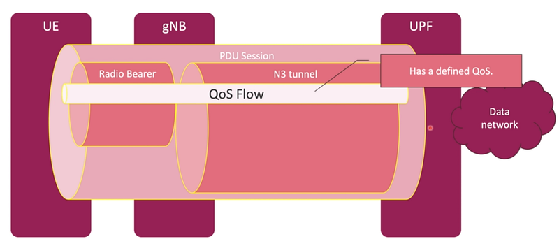
Each QoS flow defines QoS specification so it can be optimized for bursty traffic or steady traffic or high-reliability traffic.
5G architecture supports 3 different types:
GBR — This is used for applications that require a guaranteed bit rate, for example, it requires a guaranteed bit rate so the device is not interrupted during the conversation.
Non-GBR — This is used for traffic that is busty, for example, when we browse on the internet or when we download a file, in these cases, there is no steady data rate that’s required.
Delay Critical — This is used for mission-critical applications for example, for self-driving cars, for remotely controlling a robot, etc.
If UE1 and UE2 are both sending the same amount of data, it’ll be evenly split between the two. But if UE1 starts sending a huge amount of data (high bit rate) this will impact the other UEs in the cell’s ability to send data over the air as it’s a shared resource. So if UE2 needs to send a stream of small but important data over the air interface, while UE2 is sending huge amounts of data, we’d have a problem.
While UE1 can continue sending but the eNB will schedule fewer resource blocks to it as it’s reserved some for UE2’s data flow. This is known as GBR.
When the PDU session is created or modified, the 5G network provides the UE with the QoS flow description.

5QI — 5G QoS Identifier for each QoS flow
Allocation and retention priority — this is used when a UE is roaming(moving aimlessly) and the new cell has to prioritize if it can accommodate a device coming into the cell.
GBR
GFBR — guaranteed flow bit rate, for example, we need a certain amount of kilobits per second as a guaranteed bit rate for the voice call to maintain its quality.
MFBR — maximum flow bit rate, for example, for a voice call we need a minimum bit rate for guaranteeing the voice call, and then we have a maximum so that the application does not end up using too much of radio access network resources.
Maximum packet loss rate that is allowed in the UL and DL.
Delayed critical resource using GBR profiles.
Non-GBR
RQI — Reflective QoS Identifier, this indicates if the device should use the same QFI in the UL as it receives in the DL
Session AMBR and UE AMBR — It specifies what is the maximum bit rate allowed on a session-level and on a UE level QoS flow.

Multiplexing in QoS

At the device, on the application level, and at the internet site(data network), we have IP flows.
The application sees only the IP and the internet also sees the IP flows in between.
There are 2 flows of multiplexing,
When the packets arrive at the UPF, and the UPF maps the IP flows into a certain QoS flow with a corresponding QFI depending on the priority.
When the packets arrive at the gNodeB, the SDAP layer maps the IP packets with the corresponding QFI to the appropriate data radio bearer.
UL QoS
There are 2 ways of controlling how the mapping is done from QoS flows to data radio bearers.
Reflective Mapping — When the device uses the same QoS flow for UL as it uses in the DL then this type of mapping is known as reflective mapping. UL reflects the DL. It has the same configuration.
Explicit Mapping — when the device is configured to use a specific QoS flow and UL bearer through RRC signaling, then is called Explicit mapping. Here the device is explicitly told to use a certain bearer and a certain QoS flow in the UL regardless of what is configured in the DL.
Example:

The device has initially a default PDU session. When the person starts using the internet, the browsing traffic needs to be assigned. The UPF is responsible for assigning the IP flows to the right QoS flows.
In addition, if there is a zoom video call and WhatsApp video call, the UPF will decide whether they can be mapped to the same QoS flow or some different QoS flow. Both the video calls are mapped to the same QoS flow as they need the same kind of treatment.
In addition, if there is a Youtube video playing, UPF would allocate a separate QoS flow because video calls are conversational while streaming is a different scenario.
From the RAN side, the SDAP is responsible for how to map different QoS flows to the corresponding radio bearer.
For conversational video applications and the video streaming application, the SDAP can decide that they both can be mapped to the same radio bearer.
In addition, if there is a telephone call using 5G, it gets its PDU session and IP address for handling the voice call, and within this proposition, it has its entry tunnel and radio bearer.
SDAP supports that in NR by multiplexing the QoS flows to the different radio bearers.